Summary: Dynamic Host Configuration Protocol (DHCP) is a critical protocol for modern network management, especially in segmented environments. This in-depth technical article discusses the implementation of DHCP multiple VLAN configuration using the router-on-a-stick architecture on Cisco devices. We will explore the concepts of 802.1Q trunking, DHCP relay mechanisms, packet flow analysis, and provide complete CLI commands for configuration and troubleshooting. This guide is designed for network administrators looking to optimize IP management in multi-VLAN infrastructure efficiently and securely.
In medium to large corporate networks, segmentation using Virtual LANs (VLANs) is standard for enhancing security, performance, and traffic management. However, each VLAN requires a unique IP address block (subnet). Manually managing IP addresses in each subnet is an inefficient and error-prone task. This is where the role of DHCP multiple VLAN configuration becomes a strategic solution.
DHCP operates at the application layer using UDP port 67 (server) and 68 (client). In a multi-VLAN scenario, DHCP broadcasts from a client in one VLAN will not be forwarded to other VLANs by default. Therefore, an intermediary—usually a router or layer 3 switch—is required to act as a DHCP Relay Agent. The router will forward these DHCP broadcast messages to the specified DHCP server, which can be on a different subnet or integrated into the router itself.
The communication flow in a DHCP multiple VLAN configuration follows the DORA (Discover, Offer, Request, Acknowledge) process, modified for a trunked environment:
- DHCP Discover (Broadcast): A client in VLAN 10 sends a DHCPDISCOVER message as a layer 2 broadcast.
- VLAN Tagging: The switch adds an 802.1Q tag (VLAN ID 10) to the Ethernet frame before sending it out the trunk port.
- Trunk Transport: The tagged frame is forwarded over the trunk link to the router.
- Sub-interface Processing: The router, based on the VLAN ID in the tag, receives and processes the frame on the appropriate sub-interface (e.g., GigabitEthernet0/0.10).
- DHCP Offer (Unicast): The router, acting as the DHCP server, responds with a DHCPOFFER containing an IP address from the 192.168.10.0/24 pool.
- Address Assignment: The client finally receives a DHCPACK packet containing the IP address, subnet mask, default gateway (192.168.10.1), and DNS information.
Analysis of Encapsulation and Packet Flow
A deep understanding of encapsulation is crucial for troubleshooting. Here are the protocol layers involved in a DHCP multiple VLAN configuration:
| OSI Layer | Key Component | Function in Multi-VLAN DHCP |
| Data Link (L2) | 802.1Q Header | Carries VLAN ID information (12-bit) in a 4-byte tag inserted between the source MAC address and EtherType. |
| Network (L3) | IP Header / Helper Address | Converts DHCP broadcast packets into unicast so they can be routed between subnets if the DHCP server is on another network. |
| Transport (L4) | UDP Port 67/68 | Standard ports for communication between server (67) and client (68). |
| Application (L7) | DHCP Options (Field 55) | Carries additional configuration parameters such as DNS address, domain name, lease time, and TFTP server address (for VoIP). |
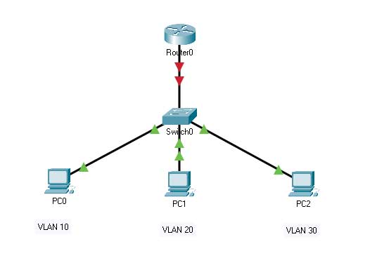
Switch Configuration Implementation
Switch configuration involves creating VLANs and setting ports as access or trunk. A trunk port carries traffic for multiple VLANs with 802.1Q tags.
! Step 1: Create VLANs in the Switch Database
Switch# configure terminal
Switch(config)# vlan 10
Switch(config-vlan)# name Engineering
Switch(config-vlan)# exit
Switch(config)# vlan 20
Switch(config-vlan)# name Marketing
Switch(config-vlan)# exit
Switch(config)# vlan 30
Switch(config-vlan)# name Operations
Switch(config-vlan)# exit

! Step 2: Configure Access Ports (Client)
Switch(config)# interface fastEthernet 0/1
Switch(config-if)# switchport mode access
Switch(config-if)# switchport access vlan 10
Switch(config-if)# description PC-Engineering
Switch(config-if)# exit

Switch(config)# interface fastEthernet 0/2
Switch(config-if)# switchport mode access
Switch(config-if)# switchport access vlan 20
Switch(config-if)# description PC-Marketing
Switch(config-if)# exit

! Step 3: Configure Trunk Port to Router
Switch(config)# interface gigabitEthernet 0/1
Switch(config-if)# switchport trunk encapsulation dot1q  ! Important on some platforms
Switch(config-if)# switchport mode trunk
Switch(config-if)# switchport trunk native vlan 999  ! Change from default VLAN 1 for security
Switch(config-if)# description TRUNK-to-Router-G0/0
Switch(config-if)# end

! Verification: Check VLAN and Trunk Status
Switch# show vlan brief
Switch# show interfaces trunk
Switch# show interfaces gigabitEthernet 0/1 switchport
Router Configuration as Central DHCP Server
The router is configured with a sub-interface for each VLAN. Each sub-interface gets an IP address that serves as the default gateway for that VLAN and runs the DHCP service.
! Step 1: Create Sub-interfaces with 802.1Q Encapsulation
Router# configure terminal
Router(config)# interface gigabitEthernet 0/0
Router(config-if)# no ip address  ! Remove IP address from physical interface
Router(config-if)# no shutdown
Router(config-if)# exit

! Sub-interface for VLAN 10
Router(config)# interface gigabitEthernet 0/0.10
Router(config-subif)# description DHCP-Server-for-VLAN10-Engineering
Router(config-subif)# encapsulation dot1Q 10  ! Must match VLAN ID on switch
Router(config-subif)# ip address 192.168.10.1 255.255.255.0
! If using an external DHCP server, use: ip helper-address <dhcp-server-ip>
Router(config-subif)# exit

! Sub-interfaces for VLAN 20 and 30 (similar configuration)
Router(config)# interface gigabitEthernet 0/0.20
Router(config-subif)# encapsulation dot1Q 20
Router(config-subif)# ip address 192.168.20.1 255.255.255.0
Router(config-subif)# exit

Router(config)# interface gigabitEthernet 0/0.30
Router(config-subif)# encapsulation dot1Q 30
Router(config-subif)# ip address 192.168.30.1 255.255.255.0
Router(config-subif)# exit

! Step 2: Configure DHCP Pools for Each VLAN
Router(config)# ip dhcp pool VLAN10_POOL
Router(dhcp-config)# network 192.168.10.0 255.255.255.0
Router(dhcp-config)# default-router 192.168.10.1
Router(dhcp-config)# dns-server 8.8.8.8 1.1.1.1  ! Primary and secondary DNS
Router(dhcp-config)# domain-name company.local
Router(dhcp-config)# lease 8  ! Lease time of 8 days
Router(dhcp-config)# option 150 ip 192.168.10.100  ! Example for TFTP server (VoIP)
Router(dhcp-config)# exit

! Exclude address ranges that should not be distributed (for static devices)
Router(config)# ip dhcp excluded-address 192.168.10.1 192.168.10.10
Router(config)# ip dhcp excluded-address 192.168.10.250 192.168.10.254

! Repeat the same process for VLAN 20 and 30 pools
Router(config)# ip dhcp pool VLAN20_POOL
Router(dhcp-config)# network 192.168.20.0 255.255.255.0
Router(dhcp-config)# default-router 192.168.20.1
... (and so on)

! Step 3: Enable Inter-VLAN Routing (if needed)
Router(config)# ip routing  ! Ensure IPv4 routing is globally active
In-depth Troubleshooting and Verification
After configuration, multi-level verification is highly recommended to ensure the success of the DHCP multiple VLAN configuration.
! 1. Verify Interface and VLAN Status on Router
Router# show ip interface brief | include 0/0.  ! Check sub-interface status
Router# show vlans  ! Detailed VLAN to sub-interface mapping

! 2. Verify DHCP Bindings and Statistics
Router# show ip dhcp binding  ! List all leased addresses with client MAC
Router# show ip dhcp pool  ! Check utilization of each pool (used/free)
Router# show ip dhcp server statistics  ! Packet and error statistics

! 3. Real-Time Debugging (Use with caution in production)
Router# debug ip dhcp server packet  ! View DHCP packet exchange (DORA)
Router# debug ip dhcp server events   ! View events like lease creation/renewal

! 4. Verification from Client Side and Connectivity
! On the PC client, use OS-specific commands:
!   Windows:   ipconfig /all
!   Linux:     dhclient -v  or  journalctl -u systemd-networkd
! Then test connectivity to gateway and between VLANs (if routing is allowed):
!   ping 192.168.10.1
!   ping 192.168.20.50
Security Best Practices and Optimization
- Enable DHCP Snooping: A switch security feature to prevent rogue DHCP server attacks.
Switch(config)# ip dhcp snooping
Switch(config)# ip dhcp snooping vlan 10,20,30
Switch(config)# interface gigabitEthernet 0/1
Switch(config-if)# ip dhcp snooping trust ! Mark trunk port to router as trusted - Set Strategic Lease Time: Permanent user VLANs (PCs) can have longer leases (7-8 days), while guest VLANs should be short (1-8 hours).
- Use IP Helper Address for External DHCP Servers: For higher scalability, direct requests to a dedicated DHCP server (like ISC DHCPd or Microsoft Server).
Router(config-subif)# ip helper-address 10.0.0.100 - Monitoring and Logging: Enable syslog to record DHCP events such as address conflicts or nearly exhausted pools.

The implementation of DHCP multiple VLAN configuration with the router-on-a-stick pattern is suitable for networks with a moderate number of VLANs (up to 50-100 VLANs, depending on the router platform). For larger and more complex environments, consider an architecture based on a Layer 3 Switch as the gateway and DHCP relay, or use a dedicated DHCP server appliance for the highest performance and reliability.
By understanding the principles, configuration, and troubleshooting outlined above, you can design and manage IP address distribution that is scalable, secure, and efficient in a multi-VLAN network environment. For further reference on standards and advanced configuration, please visit the official Cisco documentation on DHCP and the IEEE 802.1Q specification.