EtherChannel on Cisco devices is a link aggregation technique that groups multiple physical ports into a single logical channel. This technology provides significant bandwidth increase, automatic redundancy, and network management efficiency. This article discusses the basic concepts, benefits, and a step-by-step guide to configuring EtherChannel using the LACP protocol.
What is EtherChannel in Cisco Networking?
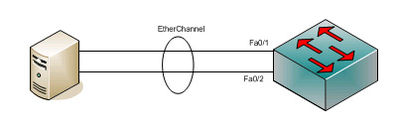
EtherChannel is a Cisco-exclusive port-channel or link aggregation architecture. This technology combines multiple physical Ethernet ports into one logical link. Its purpose is to provide high-speed connections and fault tolerance between switches, routers, and servers. An EtherChannel group can consist of 2 to 8 active ports with Fast Ethernet, Gigabit Ethernet, or 10-Gigabit Ethernet speeds. This configuration also supports ports in standby mode for failover.
Benefits of Implementing EtherChannel
Implementing EtherChannel offers several main advantages. The first benefit is increased aggregate bandwidth. By combining eight active ports, total bandwidth can reach 800 Mbps, 8 Gbps, or 80 Gbps. This speed depends on the type of ports used.
The second benefit is high redundancy and reliability. The Spanning Tree Protocol (STP) treats the entire group as one logical connection. Therefore, the failure of one physical link will not disrupt the network connection. Traffic will automatically be redirected to the remaining active links. Additionally, this technology simplifies configuration management.
Protocols for Forming EtherChannel: PAgP and LACP
Cisco supports two protocols for channel formation negotiation. The first is the Port Aggregation Protocol (PAgP), which is a Cisco-exclusive protocol. The second is the Link Aggregation Control Protocol (LACP). LACP is an open industry standard based on the IEEE 802.3ad specification (now merged into IEEE 802.1AX). This protocol allows interoperability with other vendors’ devices. Currently, LACP is more recommended for heterogeneous network environments.
Guide to Configuring EtherChannel Using LACP
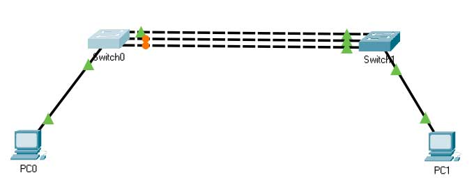
Below are the steps to configure EtherChannel LACP between two Cisco switches. Ensure cables are connected correctly. This configuration uses the default VLAN. First, check the interface and STP status on the switch before configuration.
Switch0#show spanning-tree

Interface        Role Sts Cost      Prio.Nbr Type
---------------- ---- --- --------- -------- --------------------------------
Fa0/1            Root FWD 19        128.1    P2p
Fa0/2            Altn BLK 19        128.2    P2p
Fa0/3            Altn BLK 19        128.3    P2p
The output shows interfaces Fa0/2 and Fa0/3 in a BLOCK state by STP. This mechanism prevents network loops. However, the result is that only one link is used. EtherChannel technology overcomes this issue. All links will be bundled, and STP will only see one logical channel.
Step 1: Configuration on Switch0
Switch0>enable
Switch0#configure terminal
Switch0(config)#interface range fastEthernet 0/1 - 3
Switch0(config-if-range)#channel-group 1 mode active
Switch0(config-if-range)#exit
Step 2: Configuration on Switch1
Switch1>enable
Switch1#configure terminal
Switch1(config)#interface range fastEthernet 0/1 - 3
Switch1(config-if-range)#channel-group 1 mode active
Switch1(config-if-range)#exit
The mode active command activates LACP in active negotiation mode. The switch will send LACP packets to form the channel. Passive mode (passive) only responds to packets from the active side. After configuration, no ports are blocked by STP.
Verifying EtherChannel Configuration
Use the following command to verify the EtherChannel group status. Ensure all ports are in the (P) state, which means bundled in the port-channel.
Switch0#show etherchannel summary
Flags:  D - down        P - in port-channel
        I - stand-alone s - suspended
        H - Hot-standby (LACP only)
        R - Layer3      S - Layer2
        U - in use      f - failed to allocate aggregator

Number of channel-groups in use: 1
Number of aggregators:           1

Group  Port-channel  Protocol    Ports
------+-------------+-----------+----------------------------------------------
1      Po1(SU)         LACP      Fa0/1(P) Fa0/2(P) Fa0/3(P)
The above result shows that the EtherChannel LACP configuration was successful. All three physical ports now operate as one logical link (Port-channel 1) using the LACP protocol. Bandwidth is now aggregated and redundancy is active.
Conclusion
EtherChannel is an effective solution for increasing network connection capacity and reliability. LACP protocol, as an open standard, is the right choice for multi-vendor environments. Its configuration is relatively simple yet provides significant performance impact. By implementing this technology, network administrators can optimize existing infrastructure without massive hardware upgrades. Therefore, understanding EtherChannel LACP configuration is an essential skill for IT technicians and professionals.
Reference Sources:
Cisco: EtherChannel Technology and Configuration
IEEE Standard 802.1AX-2020 (Link Aggregation)