The RJ45 connector is the heart of modern wired Ethernet connectivity. This article provides a comprehensive breakdown of its definition, the T568A and T568B pinout standards, the fundamental differences between straight-through and crossover cables, and their relevance in building reliable LAN networks for professional, technical, and gaming needs.
In the world of computer networking, the RJ45 has become the de facto standard for Ethernet cable connectors. RJ stands for Registered Jack. This small connector plays a vital role in linking devices like computers, routers, switches, and other network equipment within a Local Area Network (LAN).
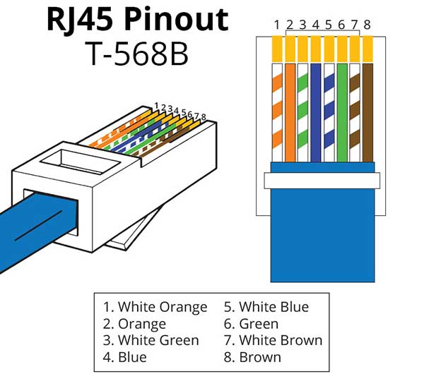
The RJ45 connector is typically terminated on the ends of twisted pair cables, such as UTP (Unshielded Twisted Pair) or STP (Shielded Twisted Pair). Each connector has 8 pins, each connecting to one of the 8 colored inner wires. The arrangement of these wire colors is not arbitrary. International standards govern it, namely T-568A and T-568B.
RJ45 Pinout Standards: T-568A vs T-568B
Wiring a cable into an RJ45 connector follows standards set by the Telecommunications Industry Association (TIA/EIA). The two most common standards are T-568A and T-568B. Their main difference lies in the order of the green and orange wire pairs.

The updated TIA/EIA 568-B standard (including revisions like 568-B.2-1) is now more dominant, especially for new installations and supports the performance of higher cable categories like Cat 6, Cat 6A, and even Cat 8 which still use the RJ45 interface. Standard selection must be consistent throughout the network for optimal performance.
Ethernet Cable Types Based on RJ45 Configuration
Based on the wire arrangement configuration at both ends of the RJ45 connector, Ethernet cables are divided into two main types: Straight-Through and Crossover. Understanding this is crucial to avoid connection errors.
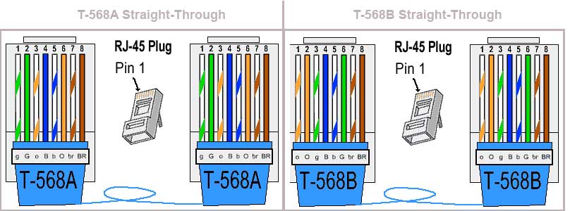
Straight-Through Cable (Patch Cable)
A straight-through cable uses the same wiring standard on both ends, either entirely T-568A or entirely T-568B. This cable is used to connect devices of different types.
- Usage Example: Computer to Switch/Router, Printer to Switch, Access Point to Router.
- This type of cable is the most common on the market and used in almost all basic network installations.
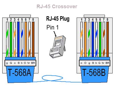
Crossover Cable
A crossover cable uses different wiring standards on each end. One end uses T-568A and the other uses T-568B. This cable is designed to connect devices of the same type directly.
- Past Usage Example: Computer to Computer, Switch to Switch without an uplink port, Hub to Hub.
- Important Note: With modern Ethernet technology like Auto-MDIX (Automatic Medium-Dependent Interface Crossover), the need for crossover cables has diminished. However, understanding this concept remains important for troubleshooting.
Theory and Application in Modern Networks
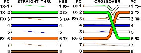
The basic principle of cable configuration is to ensure the Transmit (TX) pin of one device connects to the Receive (RX) pin of the other. Straight-through cables achieve this because the electronics inside the switch/router perform the “crossing” internally. Meanwhile, crossover cables perform that “crossing” physically within the cable.
Note that pins 4, 5, 7, and 8 (blue and brown wires) in the basic RJ45 standard for 10/100 Mbps Ethernet (Fast Ethernet) are not used for data transmission. However, in Gigabit Ethernet (1000BASE-T) and higher standards, all four wire pairs (8 wires) are used simultaneously to achieve much higher data transfer speeds. This is why high-category cables (minimally Cat 5e) and precise RJ45 termination are key to modern network performance.
By understanding the intricacies of the RJ45 connector, pinout standards, and cable types, you can confidently and accurately design, build, and troubleshoot wired Ethernet networks—from complex office setups and server infrastructure to low-latency gaming networks.